v Return to BEK Main Page
Assembly Instructions for the BEK v1.x


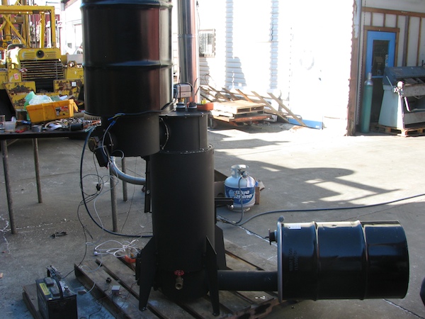
The step-by-step instructions below will guide you to turn your mysterious pile of plumbing and fabricated parts into a biochar making machine which will allow you to visit all of the curious production variables that are important in the creation and application of biochar. After you have assembled the BEK (Biochar Experimenters Kit, v1.x), visit the BEK Operation Manual for run instructions.
Table of Contents:
I) Introduction
II) Tools
A) Tools Needed
B) Sealing Materials
III) Assembly Instructions
1. Body
a) Insulation
b) Body
c) PyroBox
2. Chimney
3. Burner
a) Burner Body
b) Burner Puff Lid
c) Propane Connection
4. Install Ignitors
a) Chimney
b) PyroBox
5. Gas Cap
6. Ejector and Gas Lines
a) Bio-Oil Condensing Circuit
b) Non-Condensing Circuit
7. Raw Biomass Auger and Level Switch
8. Hopper
9. Bio Char Auger and Reservoir
10. Instrumentation
I) Introduction
II) Tools
A) Tools Needed
- 1/2'' wrench
- 9/16'' wrench
- scissors
- philips head screwdriver
- pipe wrench
- hammer
- 3/8ths drill
B) Sealing Materials Included
- fiberglass tape (high temp gasketing used on most of the larger flanges)
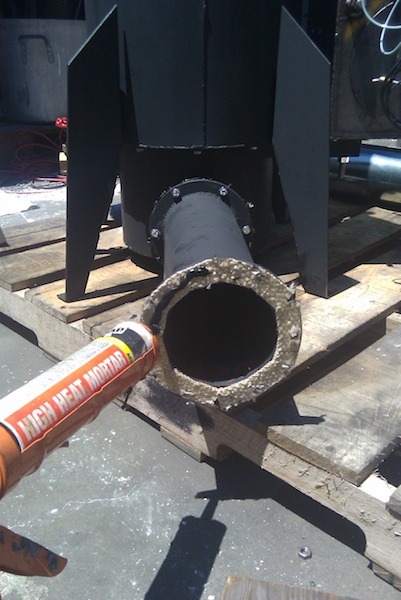
- high heat mortar (used in conjunction with the fiberglass tape to ensure sealing)
- clay gasketing (used on the smaller flanges and lids in cooler regions of the unit)
- tefflon tape (remember to use tefflon tape on all plumbing connections, except for the burner)


III) Assembly Instructions
1. Body
A) Insulation
- Through the square port on the main reactor body, fill this interstitial space with insulating material. This can be charcoal dust, ash, perlite, pumice or any other granular insulation material.


B) Char Bucket
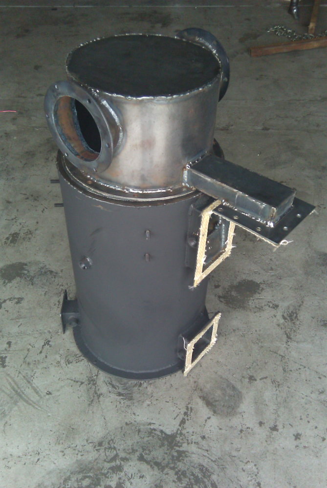
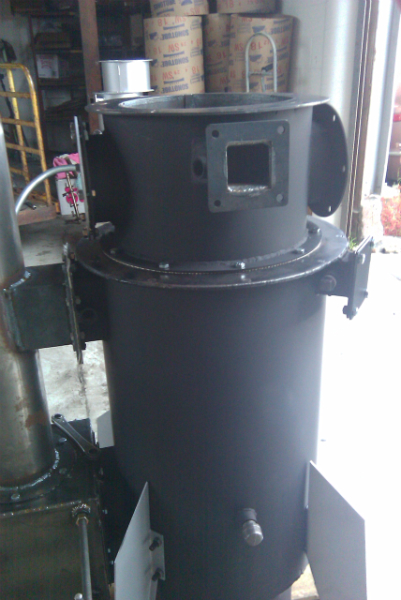
- Start with the main body of the BEK reactor. Flip the reactor upside down so that the larger port is toward the top.
- Fiber glass tape: Place one strip of the fiber glass tape around a) the flange of the Char Bucket and b) the flanges on the flue gas recycling port on the Char Bucket c) both of the two larger flanges on the reactor. Punch out the bolt holes so that the bolts will clear the tape.
- Apply a layer of high temp mortar on the fiberglass tape to ensure a gas tight seal.
- Place the ash bucket on top (this is the bottom of the reactor) with the gas recycling port lined up with the flange on the side of the reactor. Loosely thread the 3/4 x 5/16ths bolts
through the Char Bucket and the reactor. Note: Make sure the bolt holes are lined up properly. Do not force the bolt through the threads, doing this can potentially ruin the threads on the reactor.


BEK 1.2 Note:
- For the BEK v1.2, the gas ring is separate from the Char Bucket.
- Add a second layer of fiberglass tape and high temp mortar to the gas ring and insert it according to the picture below.
- Place the Char Bucket on top of the gas ring and attach with the longer 5/16ths bolts


C) PyroBox
1. Attach PyroBox to Body
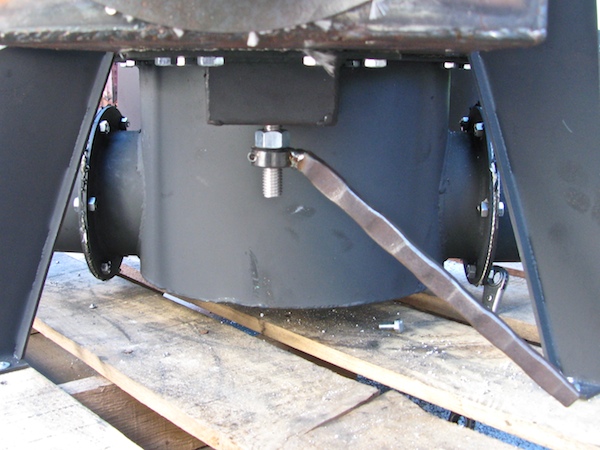
- Install the four (4) legs with the 9/16'' nuts.
- Line up the PyroBox by matching the bolt patterns of the gas recycling port and the larger retort flange on the reactor.
- Thread the 3/4 x 5/16'' bolts into the two mating flanges for the PyroBox. Tighten these bolts intermittently to make sure they are aligning properly as the bolts on both flanges are being tightened.


2. Instal Valve Handles
- Install the two valve handles on to the thread all attached to the PyroBox.
- The Sweep Gas Mode (pictured the first and second picture) has a circular valve operated by a handle on the bottom of the PyroBox.
- The Retort Mode handle is on the side of the Pyrobox.
- Make sure the valves indicate that the valve is shut by orienting it perpendicular to the flow of gases.


2. Chimney
- Place a strip of fiber glass tape onto the round flange of the chimney and punch out the holes so the bolt will clear. Apply some high temp mortar onto the fiberglass tape.
- Match the appropriate flanges of the Chimney to the PyroBox and the top retort port on the main reactor body.
- Tighten with 3/4 x 5/16'' bolts.


- Roll the stove pipe extension into its cylindrical form.
- When fitting the stove pipe extension onto the BEK Chimney, you may want to fold in the top of the Chimney with a hammer.
- Use the self tapping screws to hold the extension into place.
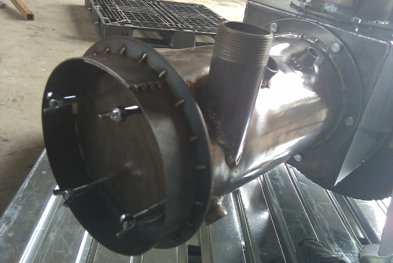
3. Burner
A. Burner Body
- Add the fiber glass tape and the high temp mortar to the burner flange in the same manner as the previous steps.
- The lighting port cap is extended with a 1/2'' x 7'' pipe nipple to keep in cooler temperatures.
- Note: A burner extension comes with the BEK. Use the burner extension between the burner and the burner body if you would like to subject the BEK reactor to lower temperatures.


B. Burner Puff Lid
i) BEK v1.2
- For the version 1.1 BEK, install the burner onto the end of the PyroBox with the threaded 1.5'' gas inlet port facing upwards.
- Attach the poof lid on the end of the burner with the four wing nuts and springs.


ii) BEK v1.3:
- For the version 1.2 BEK, attach the poof flap by utilizing three bolts from the chimney flange.
- Finish the assembly by attaching the poof cover and securing a weight (.5lb) to the end of the lever.


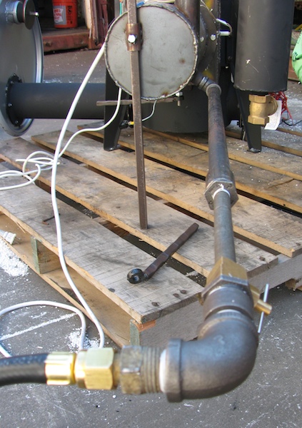
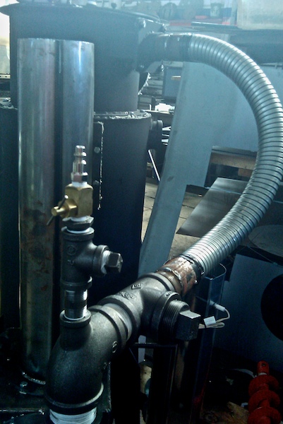
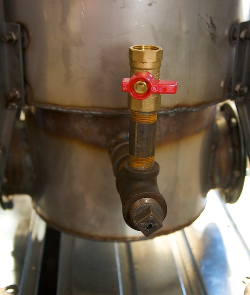
C. Propane Connection
- Connect the 1/2'' pipe elbow to the port at the underside of the burner.
- Attach an extension of 1/2'' pipe to keep the propane line away from the hot burner.
- Install the brass needle valve in line with the propane line.
- Connect the propane line after the needle valve.

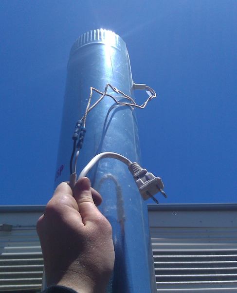
4. Install Igniters
- Strip the wires at the end of the ignitors. Connect the wires to a standard 120v wall plug.
- When the ignitors are installed, be sure to keep the wires away from hot surfaces of the BEK. You may want to use some bailing wire to secure them.
- Note: Avoid contact of High Temp Mortar to the active ignitor element, it will cause the element to burn out.


A. Chimney
- Drill a 3/8'' hole about two inches from the top of chimney extension.
- Use the self tapping screws to secure the igniter into place.


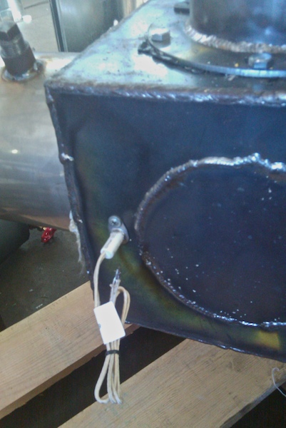
B. PyroBox
- Drill a hole into the PyroBox directly in front of the burner connection.
- Secure the ignitor into place with a screw.
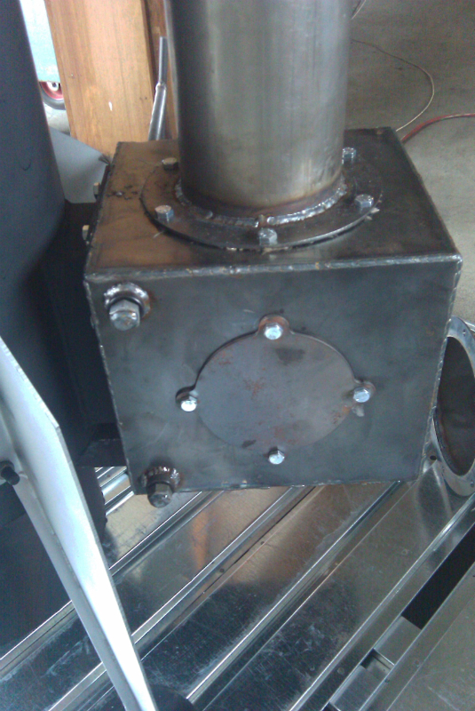
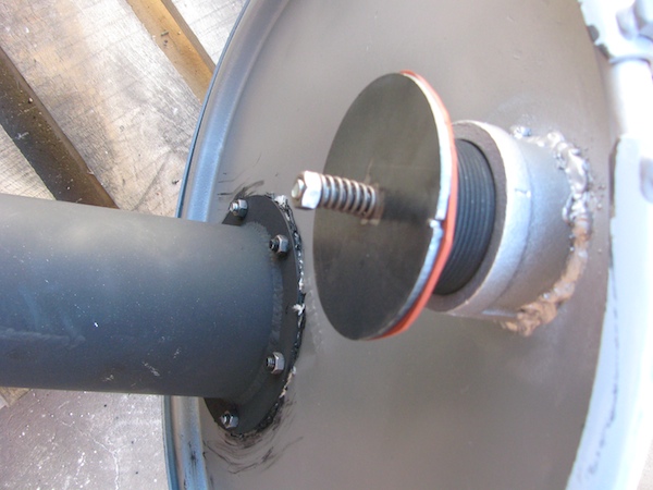
5. Gas Cap
- Orientation: The side with the wide flange is the top, from the bottom you will notice that the Gas Cap is double walled.
- Place the fiberglass tape and high temp mortar on both the top and bottom flanges of the Gas Cap, punch out the bolt holes to allow for clearance.
- Orientation: The square gas out flange will face to the right of the burner/chimney assembly.
- Use clay gasketing on the six hole flange. Attach the six hole solid plate to the nearest port toward the chimney.


6. Ejector, Gas Lines and Description of Circuits
A) Bio-Oil Circuit: Running the BEK in condensing mode will allow the collection of pyrolysis oil. Collection of pyrolysis oil/ Bio-oil may be of interest for experimentation and utilization for various projects. When in condensing mode, any remaining constituents in the gas stream will still be introduced into the burner, ensuring a clean production of biochar and pyrolysis oil.


- Attach the cyclone tube plate to the leg of the second 1.5'' plumbing T. The other two ends of the cyclone 1.5'' plumbing T will also be attached to first ejector 1.5'' plumbing T and the 1.5'' brass ball valve.
- Place the 1.5'' plug into the open end of the ejector plumbing T.
- Thread on the square gas connectors to the gas line and apply a couple strips of the clay weather stripping to the square flange.
- Wrap the flex tube two revolutions, then bolt one square flange to the cyclone, and the other to the gas cap on the top of the main body of the BEK reactor.


B) Non-Condensing Circuit: Running the BEK in clean mode will take all of the pyrolysis gases from the reactor and burn them in the burner so as not to collect or release any liquids or emissions from the biocharring process.


B) Non-Condensing Circuit: Running the BEK in clean mode will take all of the pyrolysis gases from the reactor and burn them in the burner so as not to collect or release any liquids or emissions from the biocharring process.
- Assemble the ejector according to the pictures above.
- Make sure the three plumbing T's are oriented at a 90 degree angle from each other.
- The first picture shows a 1.5'' plumbing plug at the end of the assembly. In Clean Mode, the assembly will differ from the first picture below in that the port populated by 1.5'' plumbing plug will attach to the shorter flex tube. The 1.5'' plug should then be inserted into the leg of the 1.5'' plumbing T (where the 1.5'' close nipple is located according to the first picture below).
7. Raw Biomass Auger and Level Switch
a) Auger Bucket
- Add some of the clay weather stripping between the mating flanges of the Gas Cap and the Auger Bucket.
- Use the 5/16'' nuts/bolts to attach them together.

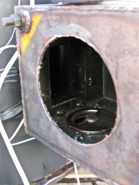
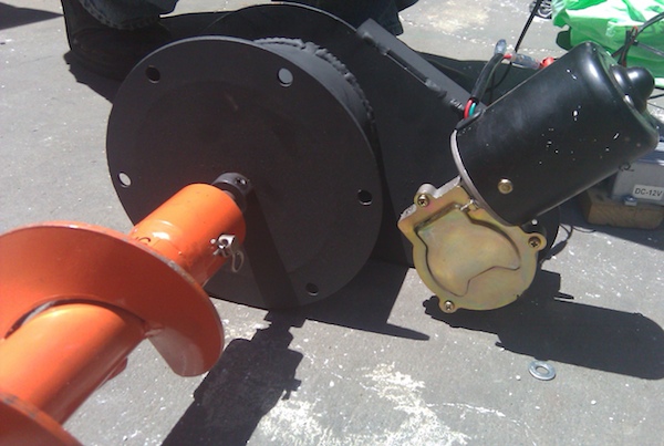
b) Biomass Auger
- Use some clay weatherstripping for the flange on the auger port on the far end.
- Make sure there is good seals around the hex bolts and the motor bearing. You may need to loosen the auger and add high heat mortar around the edges of the motor. Be careful not to get any of the mortar into the bearings of the motor.
- Insert the Auger and Auger Plate and secure with 5/16ths nuts and bolts.
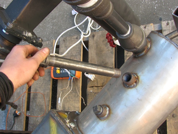
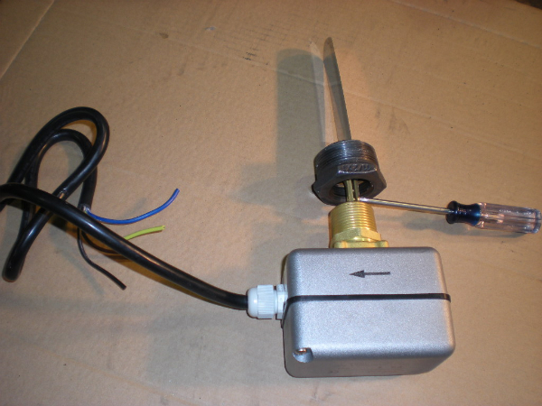
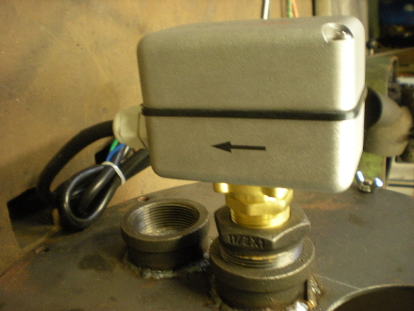
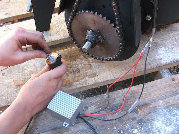
c) Level Switch
- There are three paddle sizes included with the fuel level switch. Detach the smaller paddle with a philips screw driver.
- Thread the 1- 1.5'' plumbing reducer onto the sensor.
- Attach the longer stainless steel paddle onto the sensor.


- Thread the fuel level sensor onto the middle bung of the reactor lid. The reactor lid is typically attached to the hopper barrel during shipping.
- Orientation: Make sure the arrow is pointing away from the auger, this is the direction of flow.
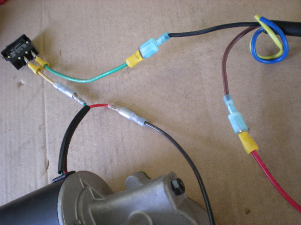
- Wire the auger to the breaker switch and then to the two wires indicating the Normally Closed (NC) configuration of the fuel level paddle switch. T
- Use 12v DC: Connect the ground of the auger motor (black) to the negative (-) lead and the common (COM/brown) to the positive (+) lead of a 12v dc source (ie: car battery).


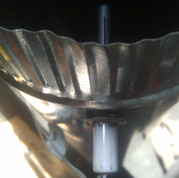
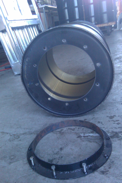
8. Hopper
- The monorator ring, shown in the first picture, will slide into the hopper barrel. Use the longer 5/16ths bolts to secure the hopper through the nuts welded to the monorator ring.
- Assemble the conical hopper insert and slide it into the hopper. This will allow the solid fuel to flow easier through the system.

- Use the springs and the wing nuts for the puff lid on the main lid of the hopper barrel.
- Attach the main lid to the hopper.
9. Biochar Auger and Reservoir
A. Biochar Auger
- Orientation: When standing in front of the burner of the BEK, the Biochar Auger will slide into the right cover on the bottom char bucket.
- Place fiberglass tape around the bottom flange of the 6 hole flange of the bottom char bucket and add a bit of hight temp mortar around the flange. Bolt the Biochar Auger assembly to the bottom using 5/16'' bolts.


- Wire the biochar auger motor by connecting the black wire (with the eyelet) of the PWM controller to the green wire on the motor. The doubled red wire will connect to the red wire on the auger motor. The single stripped red wire will connect to the positive terminal of a 12vDC battery, and the stripped black wire will connect to the negative terminal of the 12vDC battery.

B. Biochar Reservoir
- Use fiberglass tape and mortar on either side of the biochar channel.
- The lid of the char barrel char reservoir will connect to the end of the biochar channel. The 6 hole ring will fit on the inside of the lid to clamp around the char reservoir lid opening to ensure a seal. Be sure to add high temp mortar to this interface.
- Add the barrel biochar reservoir to the lid. Be sure to support the barrel from underneath.


9. Instrumentation
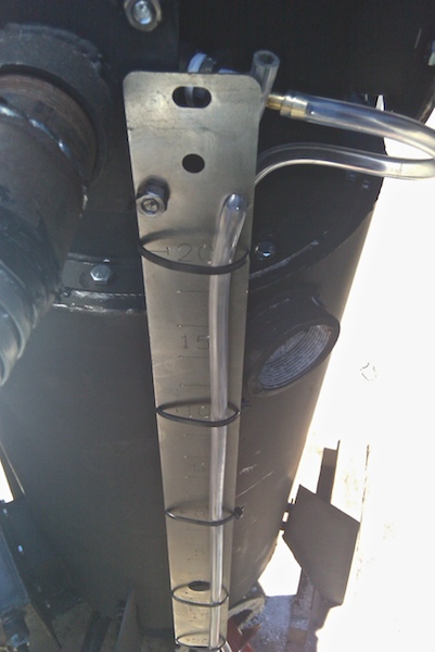
A. Manometer
- Connect the manometer face plate to the outside of the square flange on the gas cap.
- Install the manometer tube by connecting it to the brass barb on the square flange of the gas cap. Loop the manometer tube around the manometer face plate and secure with zip ties.


B. Thermocouples
- Use the appropriate plumbing reducer and compression fitting as ports for the thermocouples.
- Thermocouple placement is up to the operator, however we like to suggest them into the top of the unit to obtain the temperature of the reactor, the gas out exit port on the Gas Cap, the char reservoir or the two ports located on the retort gas entrance/exit.


Return to BEK Main Page


Comments (0)
You don't have permission to comment on this page.